Product Description
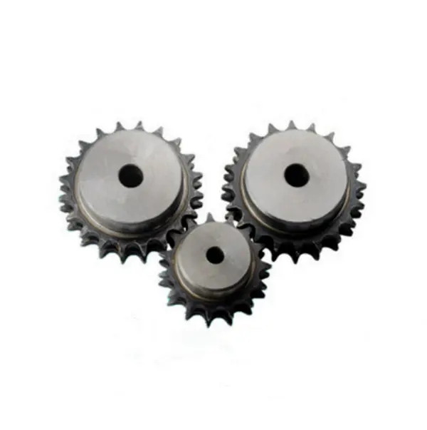
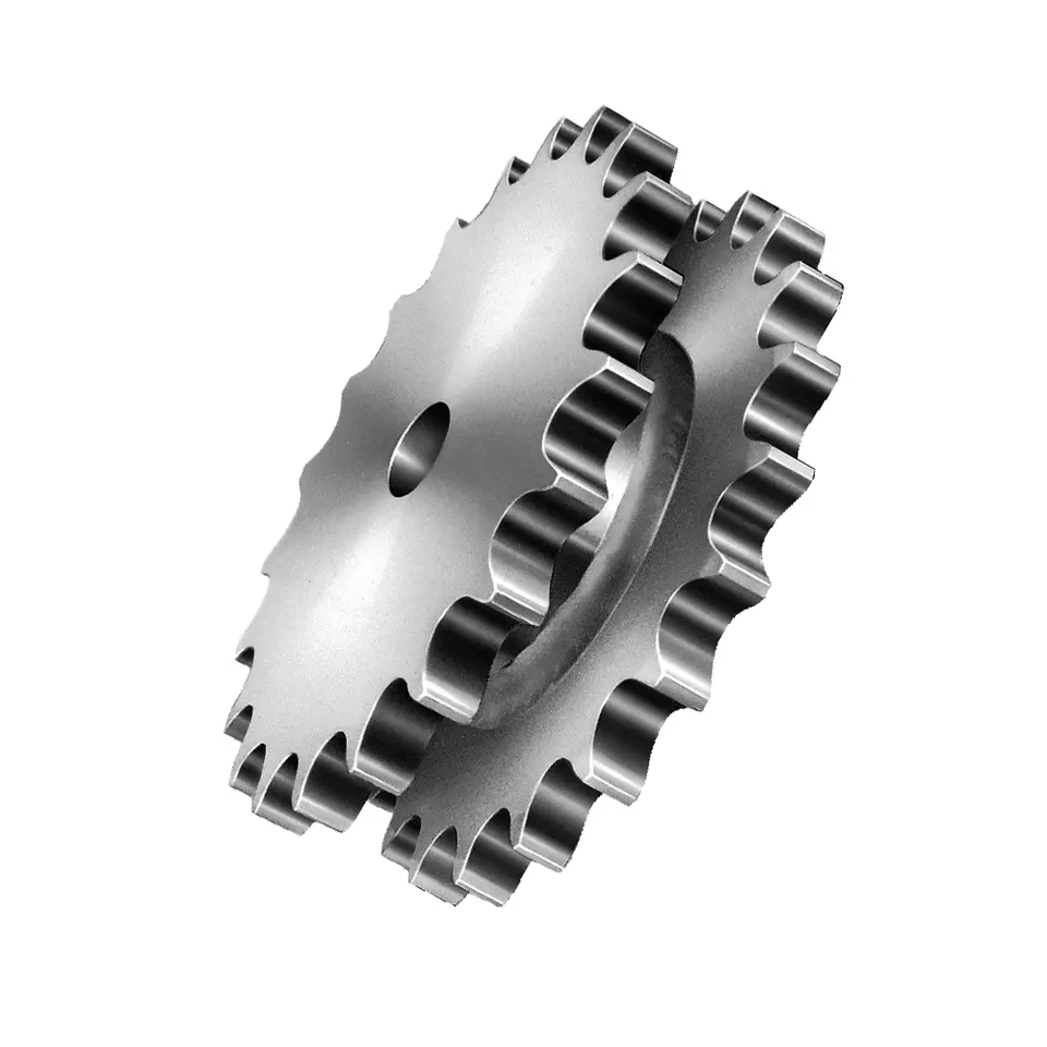
ISO Standard Made to Order & Tooth Surface Hardening Sprockets for Roller Chain
Product Description
1. Produce strictly in accordance with ANSI or DIN standard dimension
2. Material: C45 steel / Stainless Steel 304 & 316
3. Standard: ANSI, DIN, JINS, ISO, Standard America or customer drawing
4. Pilot bore, finished bore, taper bore and special bore
5. Bright surface and high precision
6. Advanced heat treatment and surface treatment craft
7. Best quality and competitive price.
8. Welcome OEM / ODM
| Product name | ISO Standard Sprocket for Roller Chain |
| Materials Available | 1. Stainless Steel: SS304, SS316, etc |
| 2. Alloy Steel: C45, 45Mn, 42CrMo, 20CrMo, etc | |
| 3. OEM according to your request | |
| Surface Treatment | Heat treatment, Quenching treatment, High frequency normalizing treatment, Polishing, Electrophoresis paint processing, Anodic oxidation treatment, etc |
| Characteristic | Fire resistant, Oil resistant, Heat resistant, CZPT resistance, Oxidative resistance, Corrosion resistance, etc |
| Design criterion | ISO DIN ANSI & Customer Drawings |
| Size | Customer Drawings & ISO standard |
| Application | Industrial transmission equipment |
| Package | Wooden Case / Container and pallet, or made-to-order |
| Certificate | ISO9001: 2008 |
| Advantage | Quality first, Service first, Competitive price, Fast delivery |
| Delivery Time | 20 days for samples. 45 days for official order. |
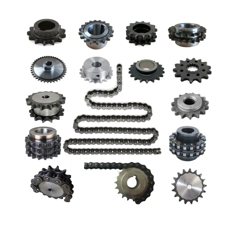
Detailed Photos
View more products,please click here…
Company Profile
/* March 10, 2571 17:59:20 */!function(){function s(e,r){var a,o={};try{e&&e.split(“,”).forEach(function(e,t){e&&(a=e.match(/(.*?):(.*)$/))&&1
| Standard Or Nonstandard: | Standard |
|---|---|
| Application: | Machinery, Marine, Agricultural Machinery, Industry |
| Hardness: | Hardened Tooth Surface |
| Material: | Alloy Steel/Stainless Steel |
| Type: | Sprocket |
| Sample: | for Free |
| Samples: |
US$ 0/Piece
1 Piece(Min.Order) | |
|---|
| Customization: |
Available
| Customized Request |
|---|
Ensuring Proper Alignment between a Wheel and its Corresponding Sprocket
Proper alignment between a wheel and its corresponding sprocket is crucial for the smooth and efficient operation of the wheel sprocket system. Misalignment can lead to increased wear, noise, and reduced performance. Here are some steps to ensure proper alignment:
- Use Precision Components: Ensure that both the wheel sprocket are high-quality, precision-manufactured components that meet the required specifications. Using well-machined components will aid in achieving better alignment.
- Check Axle Alignment: Make sure the axle or shaft on which the wheel sprocket are mounted is straight and properly aligned. Any misalignment in the axle can lead to misalignment of the wheel sprocket.
- Proper Mounting: Ensure that the wheel sprocket are securely and correctly mounted on the axle or shaft. Use appropriate fasteners and tightening techniques to prevent any movement or shifting during operation.
- Check for Parallelism: The axes of the wheel sprocket should be parallel to each other. Measure the distance between the axes at multiple points to verify parallel alignment.
- Use Alignment Tools: Alignment tools, such as laser alignment systems, can be employed to accurately align the wheel sprocket. These tools can help identify and correct misalignments effectively.
- Check Tension and Tensioner Alignment: If a tensioner is used in the system, ensure that it is properly aligned and applying the right tension to the chain or belt. Incorrect tension can cause misalignment.
- Regular Maintenance: Implement a regular maintenance schedule to check and adjust alignment as needed. Regular inspections can help identify and address alignment issues before they cause significant problems.
- Monitor Performance: Keep an eye on the performance of the wheel sprocket system. Unusual noises, vibrations, or signs of wear can indicate misalignment and should be investigated promptly.
Proper alignment is essential for the long-term performance and reliability of the wheel sprocket system. By following these steps and conducting regular maintenance, you can ensure that the wheel sprocket work together harmoniously, providing efficient power transmission and minimizing wear and tear.
Temperature Limits for wheel sprocket System’s Operation
The temperature limits for a wheel sprocket system’s operation depend on the materials used in the construction of the components. Different materials have varying temperature tolerances, and exceeding these limits can lead to reduced performance, premature wear, and even system failure.
Here are some common materials used in wheel sprocket systems and their general temperature limits:
- Steel: Steel sprockets and wheels, which are widely used in many applications, typically have a temperature limit ranging from -40°C to 500°C (-40°F to 932°F). However, the specific temperature range may vary based on the grade of steel and any coatings or treatments applied.
- Stainless Steel: Stainless steel sprockets and wheels offer improved corrosion resistance and can withstand higher temperatures than regular steel. Their temperature limit is typically between -100°C to 600°C (-148°F to 1112°F).
- Plastics: Plastic sprockets and wheels are commonly used in low-load and low-speed applications. The temperature limit for plastic components varies widely depending on the type of plastic used. In general, it can range from -40°C to 150°C (-40°F to 302°F).
- Aluminum: Aluminum sprockets and wheels have a temperature limit of approximately -40°C to 250°C (-40°F to 482°F). They are often used in applications where weight reduction is critical.
It’s essential to consult the manufacturer’s specifications and material data sheets for the specific components used in the wheel sprocket system to determine their temperature limits accurately. Factors such as load, speed, and environmental conditions can also influence the actual temperature tolerance of the system.
When operating a wheel sprocket system near its temperature limits, regular monitoring and maintenance are necessary to ensure the components’ integrity and overall system performance. If the application involves extreme temperatures beyond the typical limits of the materials, specialized high-temperature materials or cooling measures may be required to maintain reliable operation.
Calculating Gear Ratio for a wheel sprocket Setup
In a wheel sprocket system, the gear ratio represents the relationship between the number of teeth on the sprocket and the number of teeth on the wheel. The gear ratio determines the speed and torque relationship between the two components. To calculate the gear ratio, use the following formula:
Gear Ratio = Number of Teeth on Sprocket ÷ Number of Teeth on Wheel
For example, if the sprocket has 20 teeth and the wheel has 60 teeth, the gear ratio would be:
Gear Ratio = 20 ÷ 60 = 1/3
The gear ratio can also be expressed as a decimal or percentage. In the above example, the gear ratio can be expressed as 0.3333 or 33.33%.
It’s important to note that the gear ratio affects the rotational speed and torque of the wheel sprocket. A gear ratio greater than 1 indicates that the sprocket’s speed is higher than the wheel’s speed, resulting in increased rotational speed and reduced torque at the wheel. Conversely, a gear ratio less than 1 indicates that the sprocket’s speed is lower than the wheel’s speed, resulting in decreased rotational speed and increased torque at the wheel.
The gear ratio is crucial in various applications where precise control of speed and torque is required, such as bicycles, automobiles, and industrial machinery.


editor by CX 2024-01-19
Contact us
Ever-power Sprocket Co., Ltd.
Tel: +86-571-88220653/88220971
Fax: +86-571-88220651
Mail: [email protected]
WhatsApp/Wechat/Telegram/Line/Viber:

Addr: SHENHUA ROAD,HANGZHOU, ZHEJIANG , CHINA. 310030
As one of leading manufacturers, suppliers and exporters of mechanical products in China, We offer reducers, sprockets, industrial and conveyor chain, belts, pulleys, gears, racks, gearboxes, motors, PTO Shafts, taper lock Bushing, vacuum Pumps, screw air compressors and many other products. Please contact us for details.
Hours:
Monday—Friday: 9:00AM–6:00PM
Saturday & Sunday: 10:00AM–4:00PM